This is a development (evolution) of my design for the Switched Flux Transmission and you might like to peruse that section of the site for a history of how I reached this point. Some of the text on this page is copied from the information I provided for the SFT, so apologies for the repetition to anyone who is familiar with that.
When you hold two magnets with their opposite poles close to each other the magnets attract. I guess nearly everybody knows this. Similarly, if you hold your magnets with like poles facing (the same poles, North North or South South) they repel. What happens though if while they are repelling you insert a sheet of ferromagnetic (magnetisable) material, like a sheet of steel, in the gap between them? The answer, in case it didn't immediately occur to you, is that both magnets are attracted to the sheet. This is the core principle of this device.
The SFT used this principle to transmit energy from an input to an output by switching magnets between attraction and repulsion (switching flux by introducing and removing steel 'fingers' in the magnetic gap), so the theory (or my theory anyway) is that the small forces required of the input could be magnified by the power of the magnets. It proved quite difficult to design something that was rigid enough and accurate enough to test this idea but in the process of attempting that I came up with this configuration, which, at least as far as my analysis is concerned, may operate with no input energy, merely by the switching of magnetic fields that happens because of the geometry of the device.
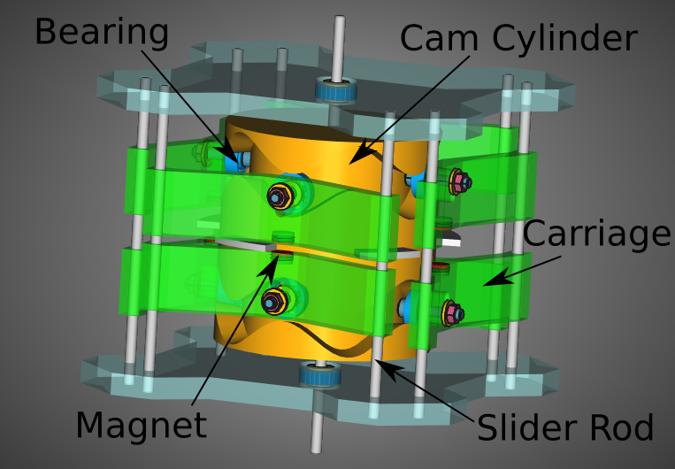
This design consists of a cylinder with two opposed sinusoidal (sign wave shaped) cam grooves cut into the sides. There are carriages mounted on rods that constrain the carriages to move backwards and forwards along the rods. Each carriage also has a magnet and a bearing. The bearing constrains the carriage to follow the cam groove. The carriages are arranged in pairs with their magnets facing each other and the magnets are mounted so that they all have the same poles facing each other. The cam cylinder also has metal tabs around the centre.
The above image labels the parts.
Here is a diagram that illustrates the principle:
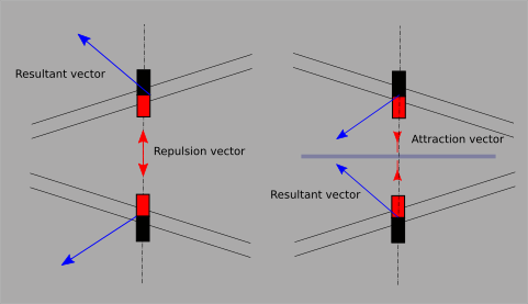
Wherever the cam tracks are converging there is a metal tab, so the magnets next to converging tracks will be attracted to the tab between them. Since the magnets are constrained to move only along the rods their associated bearing will exert a vector force on the cam track, causing the cylinder to rotate to the left.
Wherever the tracks diverge there is no metal tab and since the magnetic poles are opposed they will repel and again their bearings will exert a vector force on the cam track, also causing the cylinder to rotate to the left.
There are five peaks in the sine wave and the magnets are arranged on four sides of the cylinder. This means that when one pair of magnets is closest the opposite pair are at their most distant and the two adjacent pairs are in the middle of their travel. The closest pair of magnets will be switching to repelling (because the metal tab they were attracted to has just swept out of their gap) and the opposite pair will be switching to attraction (because a tab is just beginning to sweep into their gap.) One pair of adjacent magnets will be in the middle of their repelling phase and their opposite pair will be in the middle of their attraction phase.
Magnetic force drops off as the square of the distance from the magnet, so the closer the magnets are the more force they exert. The closest magnets will produce the most force but when they are closest the cam track is perpendicular to the force vector and an axial force vector will not cause the cylinder to turn. The opposite pair of magnets are at their most distant, meaning they will exert little force on the cam track and, to make matters worse, the track is also perpendicular at that point. However, the adjacent pairs are exerting force and at a convenient vector. This means the adjacent magnets will continue to turn the cylinder while the closest magnets are at their 'sticky' point because the vector is perpendicular. Since the track is perpendicular at that point the strong vector from the close magnets will not hinder the cylinder to turn and the moment the track ceases to be perpendicular the magnets will exert increasing (and then decreasing due to increasing distance) force on the cylinder. As the magnets on one side are decreasing their turning force the opposite pair are increasing their turning force as they get closer to each other.
I hope this is an adequate introduction to the idea. Below is a simulation of the Mk2 device running.
Good question. The Mk1 version has no control system, that is assumed to be external, perhaps involving putting sufficient load on the rotor axle to match the power of the device. Its purpose is merely as a proof of concept.
However, I have been giving some thought to a control system and that has led to Mk2.
The reason the device works - if it works at all - is because the magnets are in attraction to the tabs wherever the cam tracks are converging and in repulsion wherever the cam tracks are diverging. If the tabs were moved 36 degrees then the device would run in reverse. If, however, the tabs were only moved 18 degrees then they would line up with the point where the cam tracks change from converging to diverging. The magnets would end up in a 'hole' where their attraction to the tab prevents them from ascending the cam track either forwards or backwards.
In Mk2 the rotor is split into a number of parts: there are the upper and lower Cam Cylinders, upper and lower Tab Discs and the Control Mechanism.
In this system, the Tabs are clamped between two discs (red in the image above) and that assembly can be rotated 32 degrees relative to the Cam Cylinders (gold in the above image.) The Cam Cylinders are linked by a Link Pin. The Tab Discs are linked by their own Tab Rotor Pin, which also engages with the control mechanism's Actuator Arm. The Actuator Arm is connected to the Control Shaft, which rotates in a bore in the top Cam Cylinder.
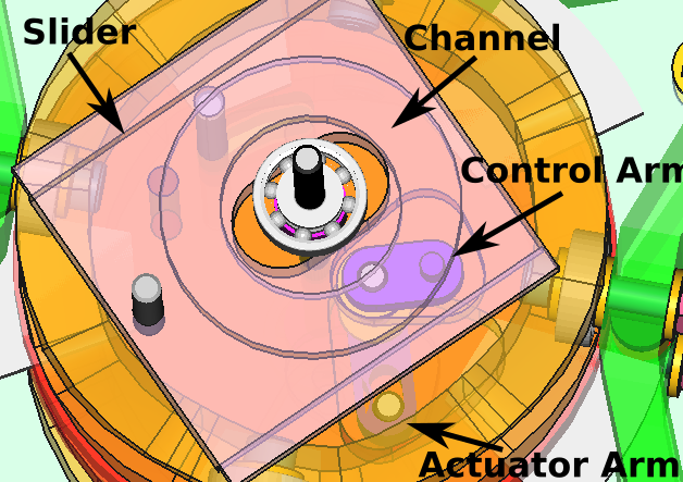
At the top of the Control Shaft is the Control Arm, which has a rod extending above the arm. That rod runs in a concentric channel under the Slider. Moving the Slider in any direction moves the centre of the channel in relation to the rod's rotation, making it eccentric, causing the Control Arm to switch towards the outside if it is currently inside or towards the inside if it is currently outside, thus it toggles the Tab alignment from advance (forward running) to stopped or from retarded (reverse running) to stopped. If the rod on the Control Arm is in the centre of the channel then the Tabs are aligned with the crossover point on the Cam Cylinders and the device is stopped. When the device is stopped the slider can be used to push the Control Arm outwards (forward running) or inwards (for reverse.)
The Actuator Arm incorporates a print-in-place leaf spring that creates a detent or 'notch' for each condition, forwards, stopped or reverse.
The video below shows the control mechanism. You will notice that if the Slider is moved it will nudge the Control Arm rod towards the centre of the channel, rotating the Control Rod and Actuator Arm, bringing the device to a stop.
Well, we don't know yet. I have to finish building it so we can see. I have about one more day of 3D printing parts and still have to find suitable magnets. Also I would rather use 5mm stainless or chrome rods but may have to settle for mild steel rods if I can't find a local source for something better.
Most of the magnetic forces work in the direction we want them to but there is a point, as the metal tab is leaving the magnetic gap, where, in addition to the repulsion vector, which works in our favour, there is a magnetic drag on the tab, trying to drag it back into the gap. At this point the magnets are quite close and it's not easy to work out which force vector will win the tug-o-war but at this same time there are two adjacent pairs of magnets - one pair in attraction and increasing their force and the other pair in repulsion with their force diminishing - that are exerting their force in a helpful direction and they may help to overcome any back-attraction of the closest magnets.
I had rather hoped that someone on one of the science forums I posted to might take a look at the geometry of the device and give some pointers as to how the force vectors will balance but it turns out, in my experience anyway, that the denizens of such fora are a sarcastic, arrogant and unfriendly lot when it comes to examining such a device; probably they feel that since free energy/overunity/perpetual motion is outlawed by thermodynamics it is not worth their time nor worth the risk of tarnishing their professional reputations. So we'll just have to build and test it ourselves.

SFMM Mk1 - Blender Cycles engine render

SFMM Mk2 - Blender Cycles engine render
Absolutely you can. I have released the complete model with an 'unlicense' license (public domain).
I developed it in FreeCAD, an astounding piece of open source, user supported, free CAD software, so to do anything with the model you'll need to install FreeCAD. You'll also need to install the Assembly 4 Workbench and Fasteners Workbench in FreeCAD to work with the complete assembly. This design was developed in FreeCAD version 0.22dev, the weekly update that will become FreeCAD 1.0, and it probably won't open in FreeCAD 21.2 stable, you'll need to install the dev version, which is available as an appimage.
Alternatively, there may be other CAD software that will import FreeCAD designs or you can import the STL files into most 3D CAD software and slicers etc.
The project is hosted on my GitHub at github.com/prajna-pranab/SFMM-Mk2 from where you can download a copy (either clone the repository or click the green '<> Code' button and click 'Download ZIP'). It would be helpful if you would star the repository.
Via Nostr: prajna@nostrcheck.me